
Magnetic induction measuring method
Use magnetic properties of materials to measure coating thickness.
Looking for a non-destructive, precise way to measure your coatings? Our solution: the magnetic induction measuring method. The prerequisite for this is a magnetic base material and a non-magnetic coating.
This is how magnetic induction measuring works.
Probes for magnetic induction measuring consist of an iron core around which an exciter coil is wound. A low-frequency alternating current (typically in the Hz range) flows through this coil. This creates an alternating magnetic field around the poles of the iron core.
When the pole of the probe approaches a magnetized object, for example a piece of iron, the iron amplifies the alternating magnetic field. A measuring coil registers this amplification as voltage. How high the voltage difference is depends on the distance between the pole and the iron part. For coated parts, this distance corresponds exactly to the coating thickness.
Where is this process used?
- Non-magnetic coating material on magnetic base material
- Electroplated layers of chromium, zinc, copper or aluminum on steel and iron
- Paint, enamel, lacquer or plastic coatings on steel and iron
What factors can influence the measurement?
All electromagnetic measuring methods are comparative. This means that the measured signal is compared with a characteristic curve stored in the device. To ensure that the result is correct, the characteristic curve must be adapted to the current conditions. This is done by adjusting the measuring device for coating thickness measurement.
The right calibration makes the difference
Factors that can strongly influence a coating thickness measurement are: the magnetic permeability of the base material, the shape of the test part, and the roughness of the surface. In addition, the operator himself can influence the result.
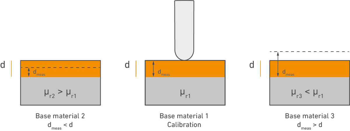
Magnetic permeability
The magnetic permeability of a material indicates how well it can adapt to a magnetic field. Materials such as iron or nickel have a high permeability. They become magnetized themselves and amplify the magnetic field.
Since magnetic permeability differs between different materials, measuring devices must be recalibrated when changing materials in order to measure the coating thickness without errors. The permeability depends on various factors, such as the steel grade, batch, part processing and temperature treatment. To avoid errors in the measuring, these factors should be taken into account.
 Magnetic permeability
Application on curved surfaces
In practice, most measurement errors occur due to the shape of the test piece. With curved surfaces, the portion of the magnetic field that passes through the air changes. For example, if a measuring device was calibrated on a flat sheet, measuring on a concave surface would result in systematically too small readings, and on a convex surface would result in systematically too large readings. The errors that arise in this way can be many times the actual value of the actual coating thickness.
 Application on curved surfaces
Application for small, flat parts
A similar effect can occur if the test part is small or very thin. In this case, too, the magnetic field reaches beyond the test part and partially runs in the air, which systematically falsifies the measurement results. To avoid these errors, you should always calibrate on an uncoated part that corresponds to your end product, if possible. This way, your coating thickness gauge will quickly provide reliable data on the thickness of the coating.
 Application for small, flat parts
Rough surfaces
With rough surfaces, the result of the coating thickness measurement can be falsified, depending on whether the probe pole is placed in the valley or on a peak of the roughness profile. With such measurements the results scatter strongly and we recommend making several repeat measurements to form a stable average. In general, coating thickness measurement on rough surfaces is only effective if the coating thickness is at least twice as high as the roughness peaks. This is the only way to measure the coating thickness without errors.
For better accuracy, we offer probes with extra large poles as well as 2-pole probes that integrate over roughness profiles to reduce measurement scatter.

 Coating thickness measurement for rough surfaces
Operating the coating thickness gauge
Also important is how the coating thickness gauge is operated. Always make sure the probe is held level above the coating and applied without pressure. The smaller the probe pole, the smaller the influence due to tilting. If the probe pole is large or flat, the influence is correspondingly greater. For better accuracy, a tripod can also be used to lower the probe onto the test part. In addition, we offer mounting aids for various probes, such as prisms for curved surfaces.
Principle: Calibration is always performed on an uncoated part of the measuring surface on which the coating thickness is also measured later.
 Operation of the coating thickness gauge
Important
To counteract erroneous measurement results, the following influences must also be taken into account:
- Indentation errors with particularly soft coatings (such as phosphate coatings).
- Scatter increases due to wear of the probe pole. We recommend carrying out regular checks.
Which standard is applied here?
Magnetic induction method according to DIN EN ISO 2178
Discover our measuring devices.