
XRF – Energy-dispersive X-ray fluorescence analysis
Fast. Simple. Non-destructive.
The X-ray beam ionizes the atoms in the sample, the detector detects the resulting fluorescence radiation, and our in-house developed software processes the signals.
This is how XRF X-ray fluorescence analysis works.
When the measuring starts, an X-ray tube emits high-energy X-rays – primary radiation. These rays strike the atoms in your sample, ejecting a near-nuclear electron from the atom and creating an imbalance. This state is unstable. Therefore, an electron from a higher shell jumps into the vacated space, emitting fluorescent radiation.
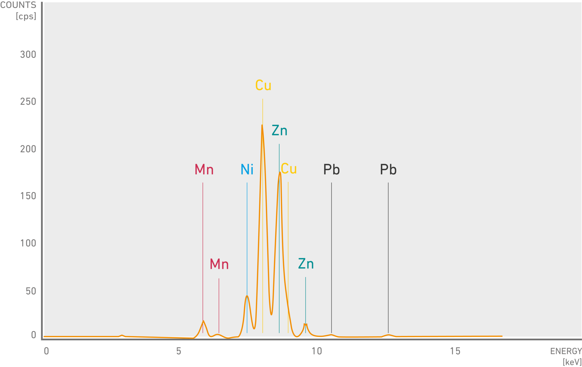
The energy level of this radiation is like a fingerprint – uniquely characteristic of the element in question. A detector measures the fluorescence radiation and digitizes the signal. Our software processes this signal and creates a spectrum: the energy of the detected photons is plotted on the x-axis, while the y-axis shows their frequency (also known as count rate). The position of the peaks in the spectrum indicate the element and the height indicates the concentration of the elements in your sample.
Where is this process used?
Unique as well as versatile: XRF analysis covers all technically relevant chemical elements from sodium to uranium.
- Measuring the thickness of coatings/dry films
- Quantitative Material analysis: Determination of the amount of a substance in the sample
e. g. gold content in jewelry
e. g. detection of elements hazardous to health such as heavy metals in consumer goods
e. g. alloys (stainless steel)
e. g. electroplating
What factors can influence the measurement?
Which components within our XRF devices have the most influence in accurate and reliable analysis?
Take a look at the basic design of our XRF instruments:
Influence of the X-ray tube on the X-ray radiation
Small parts, big effect! The "heart" of the XRF device, the X-ray generator, consists of a standard or microfocus tube with a tungsten, rhodium, molybdenum or chromium anode. The material of the X-ray tube determines the energy spectrum of the primary X-ray radiation used to excite the sample. For a wide range of applications, a tungsten anode is ideal because it produces a versatile and intensely useful spectrum. In some areas of the electronics and semiconductor industries, anodes made of molybdenum, chromium or rhodium are used.
Filter for quantitative analysis
Only what is important gets through: On its way from the anode to the sample, the primary X-ray radiation passes through a filter. Filter materials such as thin foils made of nickel or aluminum absorb part of the X-rays and thus reduce the background noise in relevant energy ranges. This results in higher sensitivity to weak signals from materials that are present in low concentrations. For example, aluminum filters help to detect lead in particularly low concentrations.
Apertures and X-ray optics
The aperture, also called collimator, is located between the X-ray tube and the sample. It limits the cross-section of the primary radiation and serves to define the measuring spot on the sample during X-ray fluorescence analysis (XRF). If you use small apertures, only a small amount of primary radiation will reach your sample, resulting in a weak fluorescence signal. To compensate for this, you have to measure for a correspondingly longer time.
Focus made by Fischer. One solution to this problem is to use polycapillary optics instead of apertures. Polycapillaries consist of glass capillaries that are bundled and can focus almost all of the primary radiation onto a small spot, much like a magnifying glass. There are only two manufacturers of such optics in the world – we are one of them.
Detector for quantitative determination of the elements
Another component of the XRF analyzer is the detector, which detects the fluorescence radiation and measures it highly precisely. The measured data is then processed by our analysis software. Depending on the detector type, various measuring tasks are possible.
Unique on the market. Only with us you have the choice of three different detector types for the optimal solution of your measuring task:
The proportional counter tube (PC) is a proven detector that has a very large active detector area with a slightly curved window. This allows high counting rates to be achieved and measurements can be made at a distance of 0 - 80 mm. The PC is particularly suitable for coating thickness measurements in the range of 1 - 30 µm and small measuring spots. In addition, the proportional counter tube has drift compensation developed by us, which gives it unique stability.
 Proportional counter tube
For more sophisticated coating thickness measurements and material analysis, the application of silicon PIN diode detectors is ideal. These semiconductor detectors offer higher energy resolution and are thus ideal for the analysis of more complex materials.
 Silicon PIN diode detectors
Higher performance XRF spectrometers use the silicon drift detector (SDD), our most powerful detector. With its particularly good energy resolution and high detection sensitivity, it offers the best performance and can detect even very low concentrations of elements in your sample. It also enables precise measuring of coatings in the nanometer range and reliable evaluation of complex multilayer tasks.
") Silicon drift detector (SDD)
Silicon drift detector (SDD)DCM method for easy and quick adjustment of the measuring distance
Control distances easily only with us: Our Distance Controlled Measurement (DCM) method offers distance-based measurement correction and a flexible measuring distance that can be continuously adjusted. Only one calibration is required for the entire measuring range, and our method enables simple measuring of complex geometry shapes and depressions without risk of collision with the measuring head.
Influence of the X-ray tube on X-ray radiation
The "heart" of our inline XRF measuring device FISCHERSCOPE® XAN® LIQUID ANALYZER is the X-ray generator. It consists of a microfocus tube with tungsten anode and beryllium window. The material of the X-ray tube determines the energy spectrum of the primary X-ray radiation used to excite the sample. For a wide range of applications, a tungsten anode is ideal because it produces a versatile and intensively usable spectrum.
Filter for quantitative analysis
Only what is important gets through: On its way from the anode to the sample, the primary X-ray radiation passes through a filter. Filter materials such as thin foils made of nickel or aluminum absorb part of the X-rays and thus reduce the background noise in relevant energy ranges. This results in higher sensitivity to weak signals from materials that are present in low concentrations. For example, aluminum filters help to detect lead in particularly low concentrations.
Air bubbles as a disturbance factor
If air bubbles are present in the analysis area, deviations in the measuring results may occur. Electroplating baths are used for electrochemical reactions in which metal ions are deposited from the solution. If air bubbles are present, metal ions can be deposited on their surface, which can lead to falsification of the analysis results. The concentration of certain metal ions in the bath is underestimated.
Air bubbles can also interfere with the flow of liquid in the bath, especially if they are located in the piping or near inlet and outlet ports. This can lead to an uneven distribution of chemicals in the bath and affect the homogeneity of the solution and falsify the analysis values.
Deposits in the measuring window
Deposits can occur in the measuring cell, which is why regular cleaning is necessary. Through fully automatic, preventive calibration, flushing and monitoring processes, we offer a solution for contamination and ensure maximum technical availability.
Further measuring solutions for bath analysis
With the appropriate accessories, the concentration of bath solutions can be measured with many of our XRF devices. For more information, contact us!
XRF – Energy-dispersive X-ray fluorescence analysis
Influence of the X-ray tube on the X-ray radiation
Small parts, big effect! The "heart" of the XRF device, the X-ray generator, consists of a standard or microfocus tube with a tungsten, rhodium, molybdenum or chromium anode. The material of the X-ray tube determines the energy spectrum of the primary X-ray radiation used to excite the sample. For a wide range of applications, a tungsten anode is ideal because it produces a versatile and intensely useful spectrum. In some areas of the electronics and semiconductor industries, anodes made of molybdenum, chromium or rhodium are used.
Filter for quantitative analysis
Only what is important gets through: On its way from the anode to the sample, the primary X-ray radiation passes through a filter. Filter materials such as thin foils made of nickel or aluminum absorb part of the X-rays and thus reduce the background noise in relevant energy ranges. This results in higher sensitivity to weak signals from materials that are present in low concentrations. For example, aluminum filters help to detect lead in particularly low concentrations.
Apertures and X-ray optics
The aperture, also called collimator, is located between the X-ray tube and the sample. It limits the cross-section of the primary radiation and serves to define the measuring spot on the sample during X-ray fluorescence analysis (XRF). If you use small apertures, only a small amount of primary radiation will reach your sample, resulting in a weak fluorescence signal. To compensate for this, you have to measure for a correspondingly longer time.
Focus made by Fischer. One solution to this problem is to use polycapillary optics instead of apertures. Polycapillaries consist of glass capillaries that are bundled and can focus almost all of the primary radiation onto a small spot, much like a magnifying glass. There are only two manufacturers of such optics in the world – we are one of them.
Detector for quantitative determination of the elements
Another component of the XRF analyzer is the detector, which detects the fluorescence radiation and measures it highly precisely. The measured data is then processed by our analysis software. Depending on the detector type, various measuring tasks are possible.
Unique on the market. Only with us you have the choice of three different detector types for the optimal solution of your measuring task:
The proportional counter tube (PC) is a proven detector that has a very large active detector area with a slightly curved window. This allows high counting rates to be achieved and measurements can be made at a distance of 0 - 80 mm. The PC is particularly suitable for coating thickness measurements in the range of 1 - 30 µm and small measuring spots. In addition, the proportional counter tube has drift compensation developed by us, which gives it unique stability.
Proportional counter tubeFor more sophisticated coating thickness measurements and material analysis, the application of silicon PIN diode detectors is ideal. These semiconductor detectors offer higher energy resolution and are thus ideal for the analysis of more complex materials.
Silicon PIN diode detectorsHigher performance XRF spectrometers use the silicon drift detector (SDD), our most powerful detector. With its particularly good energy resolution and high detection sensitivity, it offers the best performance and can detect even very low concentrations of elements in your sample. It also enables precise measuring of coatings in the nanometer range and reliable evaluation of complex multilayer tasks.
Silicon drift detector (SDD)DCM method for easy and quick adjustment of the measuring distance
Control distances easily only with us: Our Distance Controlled Measurement (DCM) method offers distance-based measurement correction and a flexible measuring distance that can be continuously adjusted. Only one calibration is required for the entire measuring range, and our method enables simple measuring of complex geometry shapes and depressions without risk of collision with the measuring head.
XRF for bath analysis
Influence of the X-ray tube on X-ray radiation
The "heart" of our inline XRF measuring device FISCHERSCOPE® XAN® LIQUID ANALYZER is the X-ray generator. It consists of a microfocus tube with tungsten anode and beryllium window. The material of the X-ray tube determines the energy spectrum of the primary X-ray radiation used to excite the sample. For a wide range of applications, a tungsten anode is ideal because it produces a versatile and intensively usable spectrum.
Filter for quantitative analysis
Only what is important gets through: On its way from the anode to the sample, the primary X-ray radiation passes through a filter. Filter materials such as thin foils made of nickel or aluminum absorb part of the X-rays and thus reduce the background noise in relevant energy ranges. This results in higher sensitivity to weak signals from materials that are present in low concentrations. For example, aluminum filters help to detect lead in particularly low concentrations.
Air bubbles as a disturbance factor
If air bubbles are present in the analysis area, deviations in the measuring results may occur. Electroplating baths are used for electrochemical reactions in which metal ions are deposited from the solution. If air bubbles are present, metal ions can be deposited on their surface, which can lead to falsification of the analysis results. The concentration of certain metal ions in the bath is underestimated.
Air bubbles can also interfere with the flow of liquid in the bath, especially if they are located in the piping or near inlet and outlet ports. This can lead to an uneven distribution of chemicals in the bath and affect the homogeneity of the solution and falsify the analysis values.
Deposits in the measuring window
Deposits can occur in the measuring cell, which is why regular cleaning is necessary. Through fully automatic, preventive calibration, flushing and monitoring processes, we offer a solution for contamination and ensure maximum technical availability.
Further measuring solutions for bath analysis
With the appropriate accessories, the concentration of bath solutions can be measured with many of our XRF devices. For more information, contact us!
Which standard is applied here?
XRF – Energy-dispersive X-ray fluorescence analysis according to IPC-4552-A/B and IPC-4556
Discover our measuring devices.